Turning a Travel Router into a Network Tap
OpenWrt Layer-2 tap with GL-MT300N-V2 Mango and USB packet capture
Contents
- What Is a Network Tap?
- A Brief Overview of Network Tap Types
- How the MT300N-V2 Tap Works
- Transparency and Behaviour on the Network
- Detectability and Stealth Characteristics
- What You Can and Cannot See
- Storage and Capture Design
- 1. Flash OpenWrt (clean)
- Download firmware
- Flash the initramfs (image
- Flash the sysupgrade image
- Set password and confirm access
- 2. Install required packages
- 3. USB setup
- 4. /etc/config/network
- 5. Disable DHCP and IPv6
- 6. Apply network changes
- 7. Capture script
- 8. Capture service
- 9. Final reboot
- 10. How to regain regain access
- About PCAP Files and Analysing the Captures
- Strengths, Limitations, and Trade-Offs
What Is a Network Tap?
A network tap is a device placed inline between two network segments for the purpose of observing traffic as it passes through. Unlike routers, firewalls, or switches performing routing and policy enforcement, a tap exists only to provide visibility. Packets enter one side, exit the other, and are duplicated for inspection without being modified or redirected.
The concept predates modern switched Ethernet and early taps were literal wire splits. Today they are purpose-built appliances designed to provide full-duplex visibility without packet loss, even at very high throughput. The defining characteristic is that traffic continues to flow normally while a copy is made available to monitoring tools.
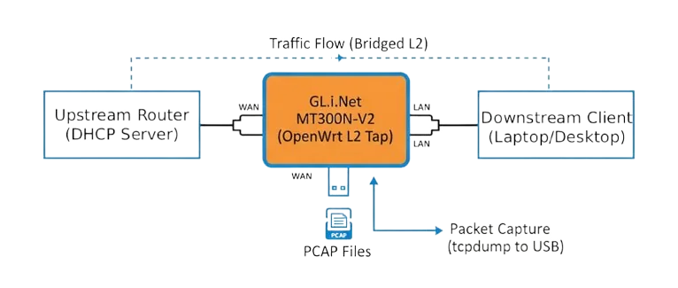
In this project, the same fundamental idea is implemented using a small OpenWrt device, the GL.iNet MT300N-V2 (Mango), configured as a transparent Layer-2 bridge with local packet capture.
A Brief Overview of Network Tap Types
Not all taps work the same way, and understanding the differences helps frame what this build does and does not aim to replace.
Passive taps are most commonly used in fibre networks. They rely on optical splitting and require no power to pass traffic. Their advantage is complete invisibility at the electrical level. Their drawback is cost, fibre-specific hardware, and signal loss that must be budgeted for.
Active hardware taps are common in copper Ethernet environments. These are powered devices that regenerate and forward traffic while copying it to monitoring ports. Many include fail-open relays so that traffic continues to pass even if the device loses power. These are what you typically find in enterprise or ISP environments.
Switch-based mirroring (SPAN) is not a tap at all, but is often used as a substitute. Traffic is copied by a managed switch and sent to a mirror port. This approach is convenient but comes with limitations like oversubscription, dropped packets under load, and the requirement that you control the switch configuration.
Software taps, like the one built here, sit somewhere between these worlds. They forward traffic actively and rely on the host CPU to both bridge and observe packets. They do not require switch configuration, but they also lack the hardware protections and guarantees of dedicated appliances.
How the MT300N-V2 Tap Works
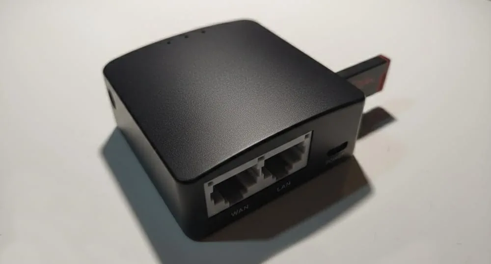
The MT300N-V2 is a small, low-power router built around a MediaTek SoC with an internal Ethernet switch. In this setup, the device is repurposed so that its LAN and WAN ports are bridged together into a single Layer-2 domain.
From the perspective of the upstream router and downstream client, nothing changes as DHCP, routing, and addressing all continue to happen elsewhere. The MT300N-V2 just forwards frames between the two ports.
At the same time, the Linux bridge interface exposes those same frames to the operating system. tcpdump attaches to that bridge in promiscuous mode and writes packet captures to a locally attached USB drive. The forwarding path and the capture path are independent; forwarding happens in the kernel bridge, while capture is observational and non-blocking.
This separation is important as if capture stops or storage fills up, traffic still continues, so the the tap becomes blind, but not disruptive.
Transparency and Behaviour on the Network
From a functional point of view, this setup behaves like a very simple unmanaged switch with two ports that has the added functionality of dumping captures. Frames are forwarded unmodified, including VLAN tags, MAC addresses, and checksums. There is no NAT, no firewalling, and no IP-level decision making in the forwarding path.
Because the device operates entirely at Layer 2, it does not appear as a hop in traceroute and does not participate in routing protocols. Endpoints establish TCP sessions exactly as they would without the tap in place.
There is, however, an important distinction between a software bridge and a purely hardware forwarding path. Forwarding decisions are made by the kernel, and packets pass through the CPU rather than dedicated switching silicon. On low-to-moderate traffic volumes this is effectively invisible. Under high packet rates, latency increases and throughput is bounded by CPU capacity. As the Mango is only a 300mb device, the throughput on a gigabit network is drastically reduced.
Detectability and Stealth Characteristics
This tap is best described as low-noise but not invisible. Even though it does not announce itself via DHCP, routing advertisements, or control protocols, it does not respond to traffic other than management access, and that management access can be isolated to a link-local address that does not interact with the rest of the network.
It is still an active device. It has a MAC address, it introduces a small amount of latency, and it forwards frames in software. In a controlled and monitored environment, those characteristics can theoretically be detected through careful timing analysis or CAM table observation.
In most home, lab, and small-network environments, the device blends in as another Ethernet hop and does not draw attention.
What You Can and Cannot See
A tap provides visibility, not decryption.
Unencrypted protocols, broadcast traffic, DNS, ARP, and metadata are all fully visible. Encrypted application payloads remain encrypted. This setup is extremely useful for understanding traffic patterns, protocol behaviour, and network issues, but it does not undermine cryptography.
This makes it well suited for diagnostics, learning, and incident investigation, rather than surveillance or content inspection.
Storage and Capture Design
Captured traffic is written locally to USB storage using a rotating ring buffer. File sizes and counts are fixed for predictable disk usage. Older data is overwritten automatically, which avoids manual cleanup and prevents storage exhaustion. This storage design reflects the realities of the hardware since the MT300N-V2 has very limited CPU and I/O bandwidth, so the capture configuration must be conservative.
The Build
This project is for diagnostics, lab use, and incident investigation on networks where you have explicit permission to monitor traffic. Do not deploy this on third-party networks without written authorisation from the network owner. Treat PCAPs as sensitive data as they may contain credentials (for unencrypted protocols), internal hostnames, MAC addresses, and metadata. Store captures securely and retain them only as long as necessary.
This guide converts a GL-MT300N V2 into a transparent inline Layer-2 network tap using OpenWrt that bridges LAN and WAN at L2, does not run DHCP or routing and captures traffic to USB with tcpdump.
1. Flash OpenWrt (clean)
To ensure we are only using what we need, we will replace the default firmware the device ships with.
Download firmware
- Go to: https://firmware-selector.openwrt.org/
- Select the GL.iNet MT300N-V2 device.
- Download both images:
- kernel (initramfs)
- sysupgrade
Flash the initramfs (image
- Set a temporary static IP on your client:
- IP: 192.168.1.10
- Netmask: 255.255.255.0
- Connect your client to the LAN port of the Mango. Hold the reset button on the Mango and power it up. The LED will blink 5 times slowly, then it will turn into a solid light, indicating the device is in recovery mode.
- Open: http://192.168.1.1/
Click Choose File, select the kernel image, then run the firmware update.
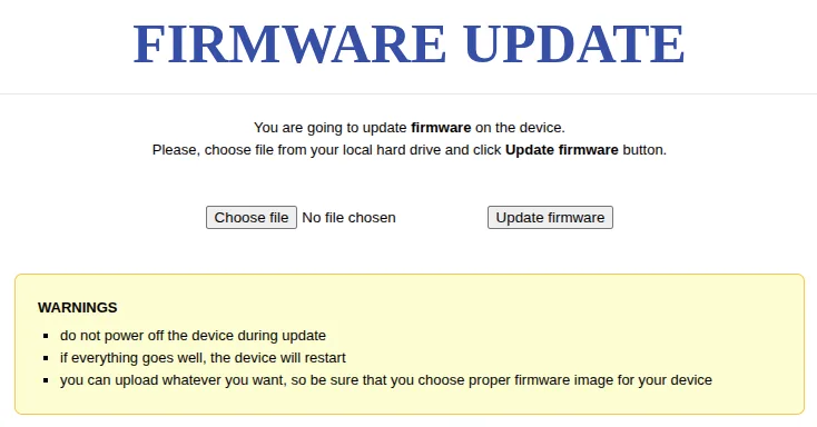
This is fairly quick (about 1 to 2 minutes). Do not unplug anything.
Flash the sysupgrade image
After the kernel flash, the device boots into initramfs mode. That means OpenWrt is running from RAM and nothing you change will persist.
- Open: http://192.168.1.1/
This should load the OpenWrt web UI now. - Log in with:
- Username: root
- Password: (blank)
- You will see the warning: System running in recovery (initramfs) mode.
- Go to Flash New Firmware Image and flash the sysupgrade file.
This can take up to 5 minutes to finish, do not unplug the device.
Set password and confirm access
- Go back to: http://192.168.1.1/
- Set the root password.
- Confirm you can SSH into the Mango from your client at 192.168.1.1, using root and the password you specified.
2. Install required packages
Temporarily connect WAN so it has internet access.
The opkg update step refreshes the package index so OpenWrt knows what versions are available. The install line pulls in tcpdump, USB storage support, ext4 filesystem support, filesystem utilities, and nano as I cannot stand using vi.
opkg update
opkg install tcpdump block-mount kmod-usb-storage kmod-fs-ext4 e2fsprogs nano
This will install:
tcpdump: packet capture engine (writes PCAP)block-mount: OpenWrt helper for persistent block device mounts via/etc/config/fstabkmod-usb-storage: kernel driver to see USB mass storage deviceskmod-fs-ext4: ext4 filesystem support in the kernele2fsprogs: ext4 utilities (fsck, tune2fs, etc.) used by mount checksnano: editing config files without suffering
3. USB setup
Format the USB stick as EXT4 on another machine.
Plug it into the Mango and verify it shows up with block info (enumerates detected block devices, partitions, UUIDs, and filesystem types). You use this to confirm the stick is visible to the kernel and is actually ext4.
block info
Create the mountpoint directory that will hold PCAP output:
mkdir -p /mnt/capture
Edit /etc/config/fstab and add the following, assuming the drive is under /dev/sda1:
config mount
        option target '/mnt/capture'
        option device '/dev/sda1'
        option fstype 'ext4'
        option options 'rw,noatime,nodiratime'
        option enabled '1'
        option enabled_fsck '1'
Apply and verify it with block mount. Then df to confirm the mount is actually active.
block mount
df -h | grep capture
You must see /mnt/capture mounted.
4. /etc/config/network
Replace the file entirely with this:
config interface 'loopback'
        option device 'lo'
        option proto 'static'
        option ipaddr '127.0.0.1'
        option netmask '255.0.0.0'

config globals 'globals'
        option ula_prefix 'fd87:da91:750f::/48'

config device
        option name 'br-tap'
        option type 'bridge'
        option stp '0'
        list ports 'eth0.1'
        list ports 'eth0.2'

config interface 'lan'
        option device 'br-tap'
        option proto 'none'

config interface 'mgmt'
        option device 'br-tap'
        option proto 'static'
        option ipaddr '169.254.99.1'
        option netmask '255.255.0.0'

config switch
        option name 'switch0'
        option reset '1'
        option enable_vlan '1'

config switch_vlan
        option device 'switch0'
        option vlan '1'
        option ports '1 6t'

config switch_vlan
        option device 'switch0'
        option vlan '2'
        option ports '0 6t'
br-tapis a Linux bridge and becomes the single Layer-2 forwarding domain.lanis set toproto 'none'so the bridge carries traffic but has no routed IP stack bound to it.mgmtassigns a link-local address on the same bridge as a management lifeline.- Switch VLAN config is kept stock so port mapping and tagging stay consistent with the MT300N-V2’s internal switch layout.
We are removing br-lan, wan, wan6 and any routed IPs, essentially turning it into a pure L2 device.
5. Disable DHCP and IPv6
This prevents the device from answering DHCP requests. In a tap build, you want DHCP to continue to originate only from the upstream router.
Edit /etc/config/dhcp and set LAN to ignore:
config dhcp 'lan'
        option interface 'lan'
        option ignore '1'
Then disable services:
/etc/init.d/dnsmasq stop
/etc/init.d/dnsmasq disable
/etc/init.d/odhcpd stop
/etc/init.d/odhcpd disable
dnsmasqis the DHCP and DNS service on OpenWrt.odhcpdprovides IPv6 RA and DHCPv6 behaviour.
Stopping and disabling both lightens the load and prevents accidental services from running on the bridge.
6. Apply network changes
sync flushes filesystem buffers so your config edits hit persistent storage before you restart networking. Then the network restart applies the bridge config.
sync
/etc/init.d/network restart
At this point, you can remove the static IP you set previously and plug the device inline (between your switch and desktop for example). Your client must get DHCP from the upstream router and you should be able to reach the internet as if the desktop was connected to the switch directly.
You will need to reconnect to the Mango (see last bit on regaining access, this will require switching back to a static IP temporarily).
7. Capture script
Create /usr/bin/tap-capture.sh:
#!/bin/sh

IFACE="br-tap"
OUTDIR="/mnt/capture"
TS="$(date '+%Y%m%d_%H%M%S')"
PCAP_BASE="$OUTDIR/tap_$TS.pcap"

# Wait for bridge
for i in $(seq 1 60); do
    ip link show "$IFACE" >/dev/null 2>&1 && break
    sleep 1
done
ip link show "$IFACE" >/dev/null 2>&1 || exit 1

# Wait for USB mount
for i in $(seq 1 60); do
    grep -q " $OUTDIR " /proc/self/mounts && break
    sleep 1
done
grep -q " $OUTDIR " /proc/self/mounts || exit 1

ip link set "$IFACE" promisc on

exec tcpdump \
  -i "$IFACE" \
  -s 256 \
  -C 50 \
  -W 20 \
  -w "$PCAP_BASE" \
  >/dev/null 2>&1
This script:
- Waits for the bridge to exist (network init race protection).
- Waits for the USB mount to be present (storage init race protection).
- Forces promiscuous mode on the bridge so tcpdump sees everything traversing it.
- Executes tcpdump as PID 1 of the script so procd supervision works cleanly.
About the tcpdump options used:
-i "$IFACE": capture on the bridge interface, not on a single port-s 256: snaplen, capture first 256 bytes of each packet (reduces I/O; headers are usually enough for most diagnostics)-C 50: rotate files at 50 MB each-W 20: keep 20 rotated files (ring buffer)-w "$PCAP_BASE": write PCAP files to USB>/dev/null 2>&1: silence stdout/stderr so logging does not fill flash
Make it executable:
chmod +x /usr/bin/tap-capture.sh
8. Capture service
Create /etc/init.d/tap-capture:
This is a procd-managed init script. START=99 pushes it late in boot order so network and mounts are likely ready. procd_set_param respawn restarts the capture script if it dies.
#!/bin/sh /etc/rc.common
START=99
USE_PROCD=1

start_service() {
    procd_open_instance
    procd_set_param command /usr/bin/tap-capture.sh
    procd_set_param respawn 3600 5 5
    procd_close_instance
}
Enable it:
chmod +x /etc/init.d/tap-capture
/etc/init.d/tap-capture enable
9. Final reboot
/etc/init.d/tap-capture stop
sync
reboot
After reboot. your client will get an IP via DHCP from the upstream, if your USB drive has a write indicator, you should see it flash as tcpdump starts capturing data and dumping it to mnt/capture under the name tap_YYYYMMDD_HHMMSS.pcap
10. How to regain regain access
As the Mango is now an L2 device without an IP address, we will leverage APIPA to be able to log back into the device (a simple backdoor that works even when inline):
On your client, change the static IP to 169.254.99.2, then SSH in with:
About PCAP Files and Analysing the Captures
PCAP files are raw packet captures. Each file contains the packets exactly as they were seen on the wire, along with timestamps as a full record of traffic.
The advantage of PCAPs is that capture and analysis are decoupled. You can collect traffic and analyse it later, as many times as needed, using different tools and filters, without touching the network again. In this setup, PCAPs are written in a rotating ring buffer. Disk usage is bounded, and older data is overwritten automatically. Each capture session is timestamped so it can be correlated with external events.
PCAPs can be analysed later using tools like Wireshark or command-line utilities such as tcpdump or tshark. Analysis usually starts broad, looking at protocols, endpoints, or timing, and then narrows down to specific conversations or events.
Encrypted traffic remains encrypted, but metadata, protocol behaviour, and traffic patterns are still visible. This is often enough to identify misconfigurations, unexpected communication, or performance issues.
Strengths, Limitations, and Trade-Offs
The strength of this approach lies in its simplicity and accessibility. It provides full-duplex visibility without requiring control of upstream infrastructure, and it does so using inexpensive, widely available hardware.
The trade-offs are fairly obvious: There is no hardware bypass, so loss of power interrupts traffic and performance is bounded by the SoC.
This build is can be useful when you need insight into traffic but cannot modify existing switches (or don't have access to them), when you want a portable diagnostic tool, or when you are experimenting and learning how networks behave under real conditions.
It is not intended to replace professional taps, but it does demonstrate that with a clear understanding of L2 behaviour, you can achieve meaningful visibility using very modest hardware.